|
|
Roger's Aquatics Pages |
|
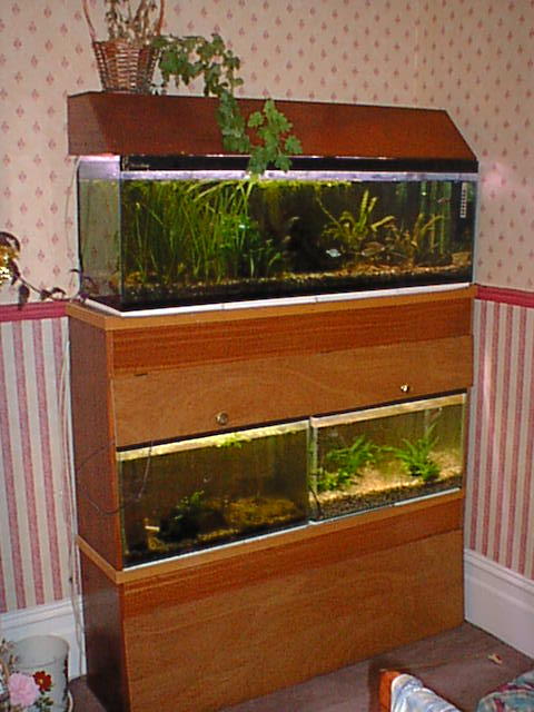
This makes a tank stand for 3 tanks, 1 48x15x12 on the top tier and 2 24x15x12 on the lower tier. The basic carcass is made from mahogany faced Chipboard. |
Schematic Plans
You will need
|
12" (305mm) Laminated or veneered Chipboard (Particle board I used Mahogany veneer | |
|
A |
1x 1280mm - Top |
|
B |
2x 1185mm - Sides |
|
C |
2x1248mm - Shelf and back. |
|
6" Laminated or veneered Chip board as above |
|
|
D |
2x1248mm - Front panels. |
|
6mm ply |
water proof quality (I used Sapele) |
|
E |
2x610x480mm - backing sheets |
|
F |
1x1275x190mm - Top door |
|
G |
1x1275x390mm - Bottom Door |
|
40x40 PSE Pine |
|
|
H |
3x 1248mm - Floor Braces & back Brace |
|
I |
3x380mm - Back Uprights |
|
50x25 PSE Pine |
|
|
J |
1x420mm - Front Upright |
|
Molding of your choice to finish |
2x1280mm 4x305mm |
|
Fittings |
12x50mm Angle Brackets
|
|
Electrics |
2x48" florescent lights
|
GENERAL NOTES
I built this stand in about 1990, and it gave excellent service. The description given is more or less exactly as I built it. The only difference is that on mine the shelf is mounted higher. This was a mistake, as a 25x15x12 fouls the back panel, and I had to have 2 24x14x12 tanks specially made.
After about 4 years the top buckled slightly, but only to the degree that can be taken up by a normal layer of expanded polystyrene. If you wished to make it for a larger tank - say 15" deep, I would recommend a strengthening bar or 2 under the top shelf. I would not use a chipboard carcass on a stand over 4ft. I did have a 6ft stand with chipboard shelves but it has 100x50mm timber uprights and braces. It wasnt very pretty as it was in the fish room so I wouldnt give a set of plans for it.
I finally broke it up in 2004 when I moved and no longer had anywhere to put it. The structure was still very sound, although the bottom of the chip board was beginning to go. This was down to abuse, for the last 2 years of its life, the stand was in the fish room, and I'm generally not to bothered about keeping the floor of the fish room dry. Eventually water had got in.
INSTRUCTIONS
Cut all the Chipboard to length. Varnish the ends to seal, use lots and make sure it really soaks in. This is to prevent water getting in after the stand is finished, as this will cause the board to swell and split.
Support the two sides (B) vertically and place the front and back floor braces (H) front and back of the bottom edge. Fix with 2 60mm Wire nails per length at each end.
Using 25mm no 6 Chipboard Screws. Take 4 "Fixit" blocks and screw 2 at each end of one length of the upper front panel (D). Fix this across the top front of the sides with the upper edge flush with the top,
Using 25mm no 6 Chipboard Screws. Take 4 "Fixit" blocks and fix 2 at each end of one length of 12" Chipboard (C). Fix this across top back of the sides, with the upper edge flush with the top.
Drill the top (A) all around the edge to take No 8 Chipboard Screws. One hole approximately every 150mm, centres 8mm from the edge. Place the top in position and screw to sides, and front and back boards using 40mm No Chipboard screws.
Take the 3 Uprights (I) and screw two angle brackets to the either side of the top of each to make a "T". Lay the frame on its front, and drill 3 holes in the back rail (H) one central and one approximately 200mm from each end. Using 75mm no 10 screws screw the 3 uprights (I) into place. Do not worry about the strength of this joint, it is under compression. Detail of Cross Bracing at back
Lay the back brace (H) across the uprights and fix into place using the angle brackets. Nail the back brace to the sides using 2x60mm wire nails at each end.
Take the Shelf (C), and drill holes along the back to take a no8 screw. These should be 20mm from the back edge, and 150mm apart. Drill a similar set of holes 8mm from the front edge. In both cases the end holes should be about 100mm from the end of the shelf. Now Fix two angle brackets to the bottom of the shelf (C) at each end, each approx. 75mm from the edges. Stand the frame upright and lay the shelf in place across the back brace. Fix to the back brace using 40mm no 8 screws, in the holes drilled. Ensure the shelf is level front to back using a spirit level, and screw the angle brackets to the sides.
Screw 2 "Fixit" blocks to each end of the lower front panel (D), and butt into place below the shelf. Screw into place through the shelf using 40mm screws. Now screw the "Fixit" blocks to either side panel.
Drill 3 holes in the end of the front brace (J), 25, 75 and 125 mm from the end, though the 50mm face. Put in place behind the lower front panel (D) and fix with screws. Fix the other end to the front brace (H) using angle brackets.
Fix the two plywood backing sheets (E) in place, using 15mm No 6 screws into the back panel (C) and25mm No 6 screws into the chipboard edges and back brace (H). Note. Do not use a single sheet, the gap between the two sheets is for wires, airline etc. NB. Do not omit or these sheets or use lighter timber - they add greatly to the rigidity of the whole assembly
Conceal the joins and screw/nail heads round the top and shelf by using the moldings, long pieces at the front to hide the join, shorter pieces each side.
Doors.
Rub down the cut edges of the doors. The appearance can be improved by chamfering the edges. Fix three hinges along the top of each door, one central, and one approx. 150mm from each end. Screw in place as shown. The lower edge of the top door should be just low enough to cover the top edge of the lower tanks. The top edge of the lower door should be at least 5mm from the floor, higher if the stand is to be placed on a deep pile carpet.
Finishing
Varnish the finished frame, using 3 coats of Polyurethane varnish. Ensure all surfaces are well covered inside and out. Pay particular attention to joints - remember, this is likely to get wet. The surface should be rubbed down after the first coat with a fine sanding paper, to prevent grain raise.
Fix the handles to either side of the upper door. You may find that you need to fit catches to either end - I did. I didnt put handles on the bottom door, as it is not supposed to be an obvious door, simply somewhere to hide air pumps, food etc.
Electrics
Caution - unless you know what you are doing seek advice.
Lighting. I used ordinary domestic fluorescent tube mountings; the mounting with tube is cheaper than an Arcadia unit of the same price. I simply kept the tubes as spares for the lights in the kitchen and replaces them with a Triton and a Sun-Glo. After 14 years or so they had started to go rusty due to moisture, but I think I can live with that.
Both tubes are hard wired to the junction box, as is the hood lighting. This is then taken to a 13-amp plug via a normal lead, with a light switch in the circuit. Actually mine does not have a normal switch, but a time switch which I think is a lot better.
The connector is a normal 13A multi-way bar. I use a 6 way, which gives 1 heater and one power filter per tank. It is mounted just under the rear light unit. Leads from the top tank come in through the rear slot, and the lead from the mains connector and the lights goes out the same way. Make sure you get one that can be screw mounted.
This is a picture of the power and lights as set up. Note that the mains connector is not a standard UK 6 way connector, but a Micromark mains adapter block. Unfortunately I don't know a supplier, although the are still available from www.micromark.co.uk It is a nice compact device, ideally suited to use in aquatics.
Install tanks and enjoy!